
| 일 | 월 | 화 | 수 | 목 | 금 | 토 |
|---|---|---|---|---|---|---|
| 1 | 2 | 3 | 4 | 5 | 6 | 7 |
| 8 | 9 | 10 | 11 | 12 | 13 | 14 |
| 15 | 16 | 17 | 18 | 19 | 20 | 21 |
| 22 | 23 | 24 | 25 | 26 | 27 | 28 |
| 29 | 30 |
- 리눅스기초#리눅스명령어#리눅스 tail#tail#모의해킹 리눅스
- QGC#QGrouncControl#GLIB오류
- 파이썬 텍스트 변환 #파이썬 공부
- 파이썬 #파이썬프로젝트 #파이썬 예시 #파이썬 파일경로 #파이썬 자동화
- 파이썬
- 논문번역 꿀팁
- 패스트 캠퍼스 #자율주행 #비전
- 파파고 꿀팁
- 파이썬#subprocess#communicate()
- 파파고 번역
- pdf 번역
- 파이썬 유튜브
- 파이썬 채팅
- 파이썬 파일 전송
- 통계 #ROC #TPR #FPR #TNR #이진분류 #Accuracy #Recall
- PDF 개행문자
- 파이썬 음성인식
- 파이썬 열
- ROS #Robotics #ROS기초
- 리눅스#모의해킹#리눅스명령어#head 명령어
- 파이썬 음성파일 텍스트 변환
- 파이선 행
- 파이썬 #
- 파이썬 엑셀 파일 읽고 쓰기
- 스트림 암호 one-time-pad 공격#보안#암호
- ROS #spin() #spinOnce() #ROS기초
- 파이썬 프로젝트
- 파이썬#파이썬경로#파이썬폴더#파이썬디렉토리
- 크롬오류#크롬검색어자동완성끄기#검색어자동완성오류#검색어자동완성 제거#검색어 노란선#검색어반복입력
- 파이썬 예시
개발자비행일지
Vibration Testing 본문
Vibration Testing
We have all heard the story of a guy who goes to his doctor and says, “It hurts when I do this,” and the doctor tells him to stop doing that. Well that might work for the guy, but not so much for products.
A product may be required to perform in aggressive usage environments, or at a minimum withstand transportation abuse. Well, with a little product analysis and supplemented with vibration testing, a product can give the designer a lot of insight into potential “hurting” areas. The calculation of board resonance modes can be a great place to start to identify the hurt.
product들도 aggressive 한 환경에서 운영되기 때문에, board resonance mode에 대한 계산은 product에 대한 hurt를 식별 하는데 사용될 수 있다.
Data has indicated that vibration and shock cause more than 20 percent of the mechanical failures in electronics. The remaining 70 percent of mechanical failures are related to thermal stresses induced by high thermal gradients, high thermal coefficients of expansion and a high modulus of elasticity. Failures are primarily from broken component lead wires, cracked solder joints, cracking of the component body, plated hole cracking, broken circuit traces, board delamination and electrical shorting. Proper design procedures for ensuring equipment survival in a shock and vibration environment are therefore essential.
The typical electronic product is composed of two major mechanical elements: an PCB chassis and the printed circuit board (PCB) assemblies.
The dynamic properties of the chassis are critical – especially the resonant frequency perpendicular to the plane of the PCB assembly – in that the chassis must not excessively amplify the vibration or shock input to the PCB.
The dynamic displacement of the PCB in turn can dramatically impact the fatigue life of the components mounted to the PCB, component leads and solder joints. The fatigue life of the various materials used for components, leads and PCBs is related to the resonant frequency of the assembly, time under vibration test, stress level, stress frequency, material resonant frequencies and fatigue properties of the materials. It is possible to estimate product fatigue life with a PCB’s natural frequency under sine-wave vibration, random vibration and shock.
When designing products it is critical to consider what David Steinberg refers to as the design octave rule; stating that the natural frequency (resonant frequency) of the chassis must be a least one octave from the natural frequency of the PCB to minimize dynamic coupling.
Example: if the PCB assembly has a 1st mode frequency of 93 Hz, then the chassis must have a frequency no closer to 93 Hz than 47 Hz or 188 Hz. Maximum stress would occur at the material resonance; the larger the physical dimension of the material the lower the resonant frequency and inversely the smaller the component the higher is its resonant frequency. Empirically the transmissibility, Q, of a printed circuit board is proportional to square root of the natural frequency. However, the resonant frequencies and the Q response should be confirmed with physical vibration testing.
PCB 기판이 작을 수록 공진 주파수가 높아지고, 기판이 클수록 낮아진다.
Typically, the higher the resonant frequency the lower the PCB displacement and the lower the stress. Vibration tests show that board reliability is reduced greatly when middle-of-the-board displacement exceeds 0.003 times the board’s width.
Many products experience potentially damaging vibration and shock stresses during shipping and transportation, and for other products will experience particularly rough handling that are transported on undeveloped roads or off road for the final installation. While many other products will experience mechanical stresses throughout their life in application and usage.
The following graphs are to provide a general understanding of vibration acceleration and frequency stress for different vehicles. These profiles are from MIL-STD-810. In general most truck, marine and rail transportation acceleration occurs in lower frequencies, while air transport has much higher frequency potential. Generally higher displacement and potentially higher stress occurs at these frequencies:
• Truck from 1 to 60 Hz
• Rail from 1 to 50 Hz
• Air from 2 to 120 Hz
Truck vibration consists predominately of frame resonance below 5 Hz, then tire transferred vibration (7-20Hz), followed by engine rotation speed (25-40Hz), and the more unpredictable vibration from rough road conditions with frequencies to 600Hz. Generally the overall truck vibration levels will increase by more than 10 dB on a dirt road relative to a highway.
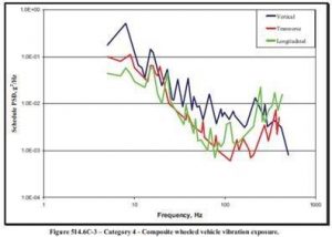
Composite Vehicle
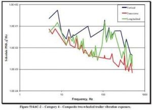
Composite 2-Wheeled Vehicle
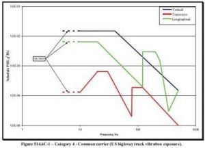
US Highway Truck
In order to reduce deflection, stiffness of a printed circuit board should be increased. This is usually done via stiffeners, additional anchor points, snubbers, staking and other mechanical means. In order to reduce stresses on PCBs or various devices on them the general guideline is to “decouple” hardware by one octave, as mentioned earlier. For instance, the relationship between the chassis to board should follow the above multiplier.
It is almost always beneficial to conduct vibration assessment tests to confirm the board and chassis resonance and strength relative to the transportation and/or usage stresses. Sine swept tests are commonly used to identify product resonances, while random vibration is better to simulate the normal transport and usage vibrations that the product would experience.
'▶ Computer Science' 카테고리의 다른 글
| 중심 극한 정리(Central Limit Theorem) (0) | 2021.03.05 |
|---|---|
| 우분투 18.04 설치 (0) | 2021.01.25 |
| Surrogate Model (0) | 2020.12.22 |
| Out-of-order Processor Pipeline 이란 (0) | 2020.12.02 |
| Direct 모드와 Indirect 모드 (0) | 2020.12.01 |


